Shadow Volumes
Technical Information
This project displays four tori rotating around a point light source. Each casts shadows on the other tori and on the walls. The effect is acheived in three passes:
-
Draw entire scene lit by ambient and a small amount of diffuse light.
This pass also sets the depth values for the visible scene. -
Draw shadow volumes into stencil buffer.
By default the shadow volumes use the "zFail" technique, with an infinite far clip plane, as described in the "Robust Stenciled Shadow Volumes" paper. - Draw scene lit with full diffuse and specular, in unshadowed areas (where stencil == 0).
Optimisations
Two-sided stencil
The demo can make use of the EXT_stencil_two_side extension, if supported. Using this, the shadow volumes can be drawn only once for each object, rather than twice. The hardware will increment/decrement the stencil buffer based on which direction the polygons are facing.
Shadow volume extrusion in a vertex program
The project also includes the option to extrude shadow volumes in a vertex program. A simple vertex program calculates the dot product between the vertex normal and the light vector, and if this is negative, the vertex is projected away to infinity. Due to the lack of position invariance between vertex programs and the standard pipeline, I also implemented a vertex program to do the lighting passes. This was made easier by the (extremely useful) automatic state tracking offered by ARB_vertex_program.
Using the zPass technique, where possible
A second rendering path uses each torus' bounding sphere to see if the shadow volume will intersect the near clip plane. If it will not, the standard "zPass" shadow volume technique is used. This means that the shadow volume "caps" are not necessary and hence leads to a 15-20% speed increase.
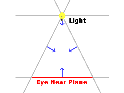
In order to calculate whether a shadow volume will intersect the near plane, six planes are created around the light source. If the occluder lies behind any of the six planes, there is no way its shadow can intersect the near plane. The planes are computed by using the inverse of the "view-projection" matrix to calculate the points in world space which will become the corners of the near clip plane. These corners and the light source position are used to create a pyramid of four planes with the light source at its apex. The fifth plane is the near clipping plane. The sixth is parallel to the near clip plane, but reversed and passing through the light source.
Here is a diagram of these planes:
Using the "zPass" technique does not increase the performance when a vertex program is used to generate the shadow volume however, since the caps are automatically generated in that case.